Bending a 6 mm² Cable at 4× the Diameter
A 6mm solar cable published with an outer diameter of 6.0 mm is limited to a bending radius of 24 mm, because the manufacturer's rule is 4 × the outer diameter. KUKA CABLE publishes that multiplier for its 1500 V range, together with the diameter itself: the same 6 mm² page gives 84 strands of 0.29 mm, a rated voltage of DC 1.8/1.8 kV, a nominal weight of 78 g/m and a spark test at 10 kV during production.
Key takeaways
- The published rule is a minimum bending radius of 4 × the outer diameter, and the 6 mm² diameter is 6.0 mm.
- Four times 6.0 mm is 24 mm, which is my own arithmetic on the published figures rather than a figure printed as such.
- The same page publishes an ambient range of −40 °C to +90 °C and a finished-cable test voltage of 6.5 kV AC for five minutes.
- Supporting data: 84 strands of 0.29 mm, a tinned copper class 5 conductor to IEC 60228 and 78 g/m.
Why the rule is written as a multiple
Expressing a bend limit as a multiple of the diameter is a way of keeping one rule across a whole family. The manufacturer applies it from 1.5 mm² to 240 mm², so the number changes with the size while the constraint stays the same. For a 6 mm² cable the published diameter of 6.0 mm sets the limit at 24 mm; for the 4 mm² build at 5.5 mm it is 22 mm, and for the 10 mm² build at 7.5 mm it is 30 mm.
Those three values are my own multiplications of published diameters. The manufacturer prints the 4 × rule and the diameters separately, which leaves the multiplication to whoever reads the datasheet — and that is exactly where a project gets it wrong, because a fitter working by eye measures the bend against the cable rather than against the diameter.
The three common sizes side by side
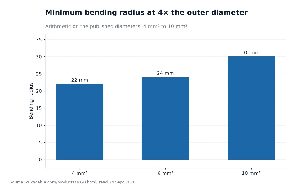
The middle bar is the one that surprises people. Moving from 4 mm² to 6 mm² raises the conductor area by half but raises the radius by only 2 mm, from 22 mm to 24 mm; moving on to 10 mm² raises the area by a further two thirds and the radius by 6 mm. That is the arithmetic of the published diameters, and it assumes each bend is a single clean curve.
The practical consequence is that 6 mm² is forgiving where 10 mm² is not. A short 90-degree turn in a narrow tray that a 6 mm² cable can take at 24 mm will be below the published limit for a 10 mm² cable, and the difference is not visible to the eye once both cables are lying in the same tray.
What 24 mm looks like on site
A 24 mm radius is a semicircle 48 mm across. That fits inside a 50 mm tray but not through a combiner-box gland that forces the cable to turn as it enters, and not around a corner where the last clip holds the cable flat against the metal. The published number is a limit on the cable, not a description of the fitting, so the fitting has to be checked against it.
Arc length is the other half of the geometry. A 90-degree turn at a 24 mm radius uses a quarter of the circumference, which is 0.25 × 2 × π × 24 mm, or about 37.7 mm of cable. My calculation, assuming a constant radius through the turn. A run with six such turns therefore consumes roughly 226 mm of cable that a straight-line drawing would not show, and a cold-weather installation with tight clearances needs that length allowed for.
Radius and insulation integrity
A bend that is too tight does more than strain the jacket. It compresses the insulation on the inside of the curve and stretches it on the outside, and both effects reduce the dielectric margin the cable was tested with. The published figures describe that margin: a spark test at 10 kV while the cable is being made, then a test voltage of 6.5 kV AC at 50 Hz for five minutes on the finished length, against a rated DC 1.8/1.8 kV.
Two mechanical figures from the same page describe the material's ability to take the bend at all. Tensile strength before ageing is published as at least 8 N/mm² and elongation before ageing as at least 125%, and the class 5 stranding pattern with 84 strands of 0.29 mm exists precisely so a 6 mm² conductor can be bent without work-hardening at the strands. A solid conductor of the same cross-section would resist the 24 mm radius instead of accepting it. The range is described against TUV 2PfG 1169/08.2007, EN 50618:2014 and IEC 62930.
| Cross-section | Overall diameter | Radius at 4 × diameter (my arithmetic) | Nominal weight | 90° turn consumes (my arithmetic) |
|---|---|---|---|---|
| 1.5 mm² | 4.6 mm | 18.4 mm | 34 g/m | 28.9 mm |
| 2.5 mm² | 5.0 mm | 20.0 mm | 45 g/m | 31.4 mm |
| 4 mm² | 5.5 mm | 22.0 mm | 59 g/m | 34.6 mm |
| 6 mm² | 6.0 mm | 24.0 mm | 78 g/m | 37.7 mm |
| 10 mm² | 7.5 mm | 30.0 mm | 130 g/m | 47.1 mm |
| 16 mm² | 8.8 mm | 35.2 mm | 190 g/m | 55.3 mm |
Worked example
Measure the run, then check the bends. On a 6 mm² string cable of 40 m with eight 90-degree turns, the turns consume 8 × 37.7 mm, or about 302 mm, so the cable to order is at least 40.3 m before terminations are added. Both figures are mine, from the published diameter and the 4 × rule, and they assume each turn is a constant-radius quarter circle with no extra slack.
Then compare the same run in 4 mm². The published diameter is 5.5 mm, the radius is 22 mm and each 90-degree turn takes 34.6 mm, so eight turns consume about 277 mm instead of 302 mm — a difference of 25 mm over the whole run. My arithmetic again. The saving in cable length is trivial, which is the useful conclusion: cross-section should be chosen for voltage drop and current, and the bending radius follows without adding a meaningful quantity of cable to the order.
Frequently asked questions
What is the bending radius for a 6 mm² solar cable?
The manufacturer publishes a minimum bending radius of 4 × the outer diameter, and the 1500 V page for the 6 mm² size gives an overall diameter of 6.0 mm, so the radius works out at 24 mm by arithmetic on those two published figures.
Does a tighter bend damage the cable immediately?
The site publishes no failure threshold for an over-tight bend. It does publish the proof the cable has passed — a spark test at 10 kV during production and a test voltage of 6.5 kV AC for five minutes on the finished cable — and a bend below the published radius puts insulation strain outside the condition those tests were carried out on.
What to write on the installation drawing
Put the radius beside every change of direction rather than a single note at the bottom of the sheet. At 6 mm² that is 24 mm, measured to the inside of the curve, and it applies at combiner entries, tray corners, conduit elbows and any point where a tie pulls the cable against a bracket. Where the geometry cannot meet it, the fix is to move the bend, widen the tray or step up a size — not to pull harder.
Then keep the paper that supports the number. Ask for the datasheet with the measured diameter, the batch record for the proof tests, and the certificate copy naming the standard. The manufacturer publishes the dimensional table on its cross-section page, the 6 mm² construction on the 1500 V product page, the mechanical tests on the published test list, and the full range in the solar cable section. A drawing annotated from those pages can be checked by the installer before a single clip goes in.
The 6 mm² bending rule and the diameters behind it come from the maker's own website, kukacable.com, read 24 Sept 2026[1].